 Features:
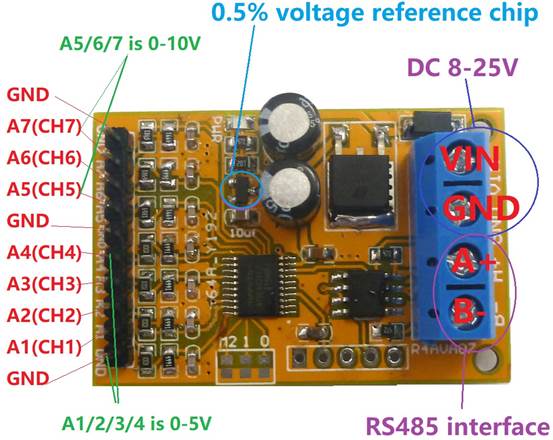
1: Operating Voltage : DC 8-25V(DC 9V 12V 15V
24V)
2: Operating Current : 10-15MA
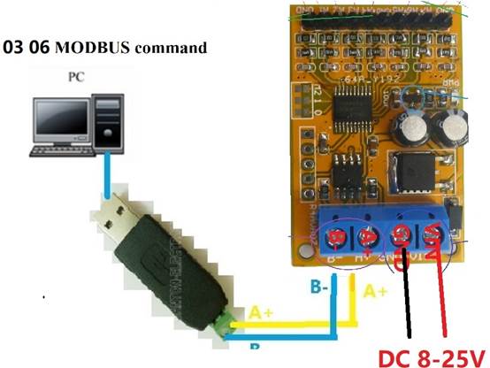
3: MODBUS
RTU Command support 03 06 function code
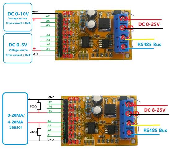
4: The A1/2/3/4 channel voltage measurement
range is 0-5V, and the A5/6/7 channel voltage measurement range is 0-10V. The
drive capability of the tested voltage source must be greater than 1MA,
otherwise the measurement cannot be accurate (MCU IO voltage cannot be
measuring)
5: Voltage measurement accuracy of 1%,
calibration can be calibrated if the error is greater than 1%
6 :MODBUS commands can be made serial
HyperTerminal (serial assistant) OR PLC Enter;
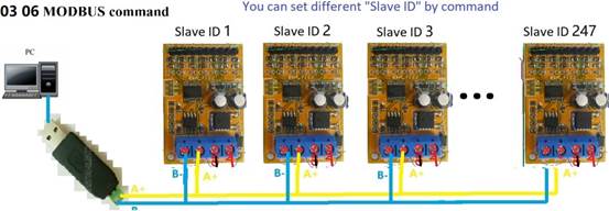
7 :Under the MODBUS command mode, it can
support up to 247 devices in parallel
8 :Size: 45 * 30 * 15mm
9 :Weight: 10 g
Modbus RTU Command Please refer to : "R4AVA07 modbus rtu protocol"
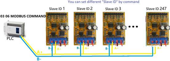
Wiring diagram:
Slave ID: Different "Sliver ID" can be
set by command, the maximum number is 247
Under the MODBUS command mode,the
slave ID must be correct
Command Description, Please
refer to " R4AVA07 modbus rtu protocol "
R4AVA07 modbus
rtu protocol
Function code
|
RS485 address (Station address) (1) |
Function (1) |
Register address (2) |
Read number (2) |
CRC16 (2) |
|
|
03 Read |
|
|
|
|
|
06 Write |
|
|
|
|
Read-only register,Read Function code Is
03 |
||||
|
Register address |
Register contents |
Number of bytes |
Units |
Remarks |
|
0x0000 |
(CH1)A1 voltage value |
2 |
0.01V |
such as: Get 0x014A Decimal 330 Voltage = 330 * 0.01 =
3.3V |
|
0x0001 |
(CH2)A2 voltage value |
|||
|
0x0002 |
(CH3)A3 voltage value |
|||
|
0x0003 |
(CH4)A4 voltage value |
|||
|
0x0004 |
(CH5)A5 voltage value |
|||
|
0x0005 |
(CH6)A6 voltage value |
|||
|
0x0006 |
(CH7)A7 voltage value |
|||
|
Read / write register;
Read function code is 03 ,Write function code is 06 |
||||
|
0x0007 |
(CH1)A1 voltage ratio |
2 |
0.1% millesimal |
This value can be
corrected when the voltage reading deviation is greater than 1%, such as: 1000 means 1:1 1010: 1% increase 990: 1% decrease |
|
0x0008 |
(CH2)A2 voltage ratio |
|||
|
0x0009 |
(CH3)A3 voltage ratio |
|||
|
0x000A |
(CH4)A4 voltage ratio |
|||
|
0x000B |
(CH5)A5 voltage ratio |
|||
|
0x000C |
(CH6)A6 voltage ratio |
|||
|
0x000D |
(CH7)A7 voltage ratio |
|||
|
0x000E |
RS485 address (Station address) |
2 |
|
Read Address 0XFF Write Address 1-247 |
|
0x000F |
Baud rate |
2 |
|
0~4 0:1200 1:2400 2:4800 3:9600(default) 4:19200 5: Factory reset |
Serial baud rate:9600(default),N,8,1
Modbus RTU Communication protocol:
1.
Read Voltage
value
Send data
|
RS485
address (Station
address) (1) |
Function
(1) |
Register
address (2) |
Read
number (2) |
CRC16(2) |
Returns
data
|
RS485
address (Station
address) (1) |
Function
(1) |
Number of bytes (1) |
data (n) |
CRC16(2) |
RS485 address(Slave ID) : 0x01~0xFE
Function
code 0x03
Register address:0x0000-0x0006,
Indicates 1-7 channel value
Read number:0x0001-0x0007
The return
of the Voltage value is two bytes,High-bit
in the former and low-bit in the post,convert it to
decimal and divided by 100, is the Voltage
value, Unit 0.01V; for example:
For
example:
Send data(RS485 address is 1):01 03 00
00 00 01 84 0A
Returns
data:01 03 02 01 4B F9 E3
01 RS485 address,03 Function,02 length,F8 E3
crc16
014B is
the Voltage value, it is converted to decimal = 331, 331/100=3.31V;
Returns
data:01 03 02 00 DB F8 1F
00DB is
the Voltage value, it is converted to decimal =219, 219/100=2.19V;
2.
Read RS485
address
Send data
|
RS485
address (Broadcast
address) (1) |
Function
(1) |
Register
address (2) |
Read
number (2) |
CRC16(2) |
Returns
data
|
RS485
address (
Broadcast address ) (1) |
Function
(1) |
Number of bytes (1) |
data (n) |
CRC16(2) |
Broadcast address 0xff
Function
code 0x03
Register address:0x000E
Read number:0x0001
For
example:
send data:FF 03 00
0E 00 01 F0 17
Returns
data:FF 03 02 00 01 50 50
FF Broadcast address,03 Function,02 length,01 is the
current module RS485 address , 50 50 crc16
Note:
When using this command, only one temperature module can be connected to the
RS485 bus, more than one will be wrong!
3.
Write
RS485 address
Send data
|
RS485
address (Station
address) (1) |
Function
(1) |
Register
address (2) |
Setting
Content (2) |
CRC16(2) |
Returns
data
|
RS485
address (Station
address) (1) |
Function
(1) |
Register
address (2) |
Register
value (2) |
CRC16(2) |
RS485 address(Slave ID) : 0x01~0xFE
Function
code 0x06
Register address:0x000E
Setting Content:2Bytes(1-247)
For
example, The current
RS485 address is 1, We need to change the RS485 address to 3:
send data(RS485 address is 1):01 06 00
0E 00 03 A8 08
Returns
data:01 06 00 0E 00 03 A8 08
4.
Read baud rate
Send data
|
RS485
address (Station
address) (1) |
Function
(1) |
Register
address (2) |
Read
number (2) |
CRC16(2) |
Returns
data
|
RS485
address (Station
address) (1) |
Function
(1) |
Number of bytes (1) |
data (n) |
CRC16(2) |
RS485 address(Slave ID) : 0x01~0xFE
Function
code 0x03
Register address:0x000F
Read number:0x0001
For
example:
send data(RS485 address is 1):01 03 00
03 00 01 74 0A
Returns
data:01 03 02 00 03 F8 45
01 RS485 address,03 Function,02 length,F8 45
crc16
03 means
the current baud rate is 9600bps
Baud rate corresponds to the number: 0: 1200 1: 2400 2: 4800 3: 9600 4: 19200
5.
Write baud rate
Send data
|
RS485
address (Station
address) (1) |
Function
(1) |
Register
address (2) |
Setting
Content (2) |
CRC16(2) |
Returns
data
|
RS485
address (Station
address) (1) |
Function
(1) |
Register
address (2) |
Register
value (2) |
CRC16(2) |
RS485 address(Slave ID) : 0x01~0xFE
Function
code 0x06
Register address:0x000F
Setting Content:2Bytes(0-4)
For
example, Change the baud rate to 4800bps:
send data(RS485 address is 1):01 06 00
0F 00 02 38 08
Returns
data:01 06 00 0F 00 02 38 08
Baud rate corresponds to the number: 0: 1200 1: 2400 2: 4800
3: 9600 4: 19200
5: Factory reset
Note: 1 The baud rate will be updated when the
module is powered up again!
2 The
factory setting can be restored when the baud rate corresponding to the number
is 5. For example: 01 06 00 0F 00 02 38 08
6.
Read
voltage ratio:
Send data
|
RS485
address (Station
address) (1) |
Function
(1) |
Register
address (2) |
Read
number (2) |
CRC16(2) |
Returns
data
|
RS485
address (Station
address) (1) |
Function
(1) |
Number of bytes (1) |
data (n) |
CRC16(2) |
RS485 address(Slave ID) : 0x01~0xFE
Function
code 0x03
Register address:0x0007-0x000D
; Indicates 1-7 channel value
Read number:0x0001-0x0006
Return
data: 0.1% millesimal
The voltage ratio can be corrected by this value when
the voltage reading deviation is greater than 1%. The default value is 1000
(3E8).
For example 1:
send data(RS485 address is 1):01 03 00
07 00 01 35 CB; 07 is Channel 1
Returns
data:01 03 02 03 E8 B8 FA
03E8 is
the voltage ratio, which is 1000 in decimal and divided by 1000=1; indicating
that channel 1 does not need to modify the voltage value.
For example 2:
send data(RS485 address is 1):01 03 00
08 00 01 05 C8; 08 is Channel 2
Returns
data:01 03 02 03 DE 38 EC
03DE is
the voltage ratio, which is 990 in decimal and divided by 1000=0.99; Indicates
that channel 2 reads 0.99 times the actual acquisition value.
7.
Set voltage
ratio
The
voltage ratio can be corrected by this value when the voltage reading deviation
is greater than 1%. The default value is 1000 (3E8).
Send data
|
RS485
address (Station
address) (1) |
Function
(1) |
Register
address (2) |
Setting
Content (2) |
CRC16(2) |
Returns
data
|
RS485
address (Station
address) (1) |
Function
(1) |
Register
address (2) |
Register
value (2) |
CRC16(2) |
RS485 address(Slave ID) : 0x01~0xFE
Function
code 0x06
Register address:0x0007-0x000D
; Indicates 1-7 channel value
Setting Content:2Bytes
Setting value: 2 bytes, unit 0.1%. When this value
is set to 1000 (3E8), the voltage value does not change.
For example 1: The actual
voltage of channel 1 is 5.00V, but the read value is
only 4.00V. The ratio deviation is 5/4=1.25, and the correction voltage ratio
is changed to 1250, which can correct the voltage.
Send frame: 01 06 00 07 04 E2 BA 82
Return frame: 01 06 00 07 04 E2 BA 82
The return frame is the same as the send frame. 07
means channel 1, 04 E2 means correction voltage ratio is 1250
For example 2: The actual
voltage of channel 1 is 4.00V, but the read value is
only 5.00V. The ratio deviation is 4/5=0.8, and the correction voltage ratio is
changed to 800, which can correct the voltage.
Send frame: 01 06 00 08 03 20 09 20
Return frame: 01 06 00 08 03 20 09 20
The return frame is the same as the send frame. 08
means channel 2, 03 20 means correction voltage
ratio is 800
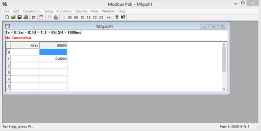
MODBUS
commands you can use "Modbus Poll" input, as shown below
(CRC check
generated automatically)
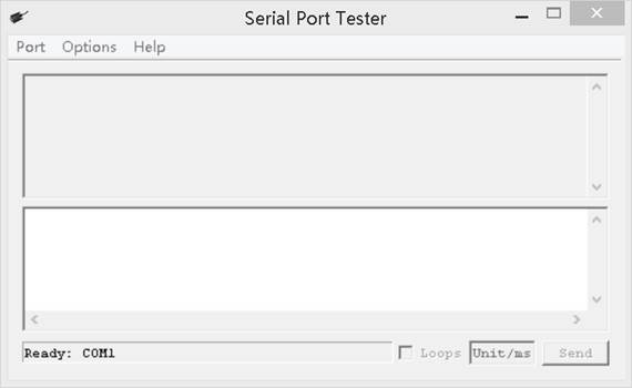
You can also use HyperTerminal serial input, as
shown below
(Manually
add CRC check)
CRC check code(C51 MCU):
const
unsigned char code auchCRCHi[256] = {
0x00,
0xC1, 0x81, 0x40, 0x01, 0xC0, 0x80, 0x41, 0x01, 0xC0, 0x80, 0x41, 0x00, 0xC1,
0x81, 0x40,
0x01,
0xC0, 0x80, 0x41, 0x00, 0xC1, 0x81, 0x40, 0x00, 0xC1, 0x81, 0x40, 0x01, 0xC0,
0x80, 0x41,
0x01,
0xC0, 0x80, 0x41, 0x00, 0xC1, 0x81, 0x40, 0x00, 0xC1, 0x81, 0x40, 0x01, 0xC0,
0x80, 0x41,
0x00,
0xC1, 0x81, 0x40, 0x01, 0xC0, 0x80, 0x41, 0x01, 0xC0, 0x80, 0x41, 0x00, 0xC1,
0x81, 0x40,
0x01,
0xC0, 0x80, 0x41, 0x00, 0xC1, 0x81, 0x40, 0x00, 0xC1, 0x81, 0x40, 0x01, 0xC0,
0x80, 0x41,
0x00,
0xC1, 0x81, 0x40, 0x01, 0xC0, 0x80, 0x41, 0x01, 0xC0, 0x80, 0x41, 0x00, 0xC1,
0x81, 0x40,
0x00,
0xC1, 0x81, 0x40, 0x01, 0xC0, 0x80, 0x41, 0x01, 0xC0, 0x80, 0x41, 0x00, 0xC1,
0x81, 0x40,
0x01,
0xC0, 0x80, 0x41, 0x00, 0xC1, 0x81, 0x40, 0x00, 0xC1, 0x81, 0x40, 0x01, 0xC0,
0x80, 0x41,
0x01,
0xC0, 0x80, 0x41, 0x00, 0xC1, 0x81, 0x40, 0x00, 0xC1, 0x81, 0x40, 0x01, 0xC0,
0x80, 0x41,
0x00,
0xC1, 0x81, 0x40, 0x01, 0xC0, 0x80, 0x41, 0x01, 0xC0, 0x80, 0x41, 0x00, 0xC1,
0x81, 0x40,
0x00,
0xC1, 0x81, 0x40, 0x01, 0xC0, 0x80, 0x41, 0x01, 0xC0, 0x80, 0x41, 0x00, 0xC1,
0x81, 0x40,
0x01,
0xC0, 0x80, 0x41, 0x00, 0xC1, 0x81, 0x40, 0x00, 0xC1, 0x81, 0x40, 0x01, 0xC0,
0x80, 0x41,
0x00,
0xC1, 0x81, 0x40, 0x01, 0xC0, 0x80, 0x41, 0x01, 0xC0, 0x80, 0x41, 0x00, 0xC1,
0x81, 0x40,
0x01,
0xC0, 0x80, 0x41, 0x00, 0xC1, 0x81, 0x40, 0x00, 0xC1, 0x81, 0x40, 0x01, 0xC0,
0x80, 0x41,
0x01,
0xC0, 0x80, 0x41, 0x00, 0xC1, 0x81, 0x40, 0x00, 0xC1, 0x81, 0x40, 0x01, 0xC0,
0x80, 0x41,
0x00,
0xC1, 0x81, 0x40, 0x01, 0xC0, 0x80, 0x41, 0x01, 0xC0, 0x80, 0x41, 0x00, 0xC1,
0x81, 0x40
} ;
const
unsigned char code auchCRCLo[256]
= {
0x00,
0xC0, 0xC1, 0x01, 0xC3, 0x03, 0x02, 0xC2, 0xC6, 0x06, 0x07, 0xC7, 0x05, 0xC5,
0xC4,0x04,
0xCC,
0x0C, 0x0D, 0xCD, 0x0F, 0xCF, 0xCE, 0x0E, 0x0A, 0xCA, 0xCB, 0x0B, 0xC9, 0x09,
0x08, 0xC8,
0xD8,
0x18, 0x19, 0xD9, 0x1B, 0xDB, 0xDA, 0x1A, 0x1E, 0xDE, 0xDF, 0x1F, 0xDD, 0x1D,
0x1C, 0xDC,
0x14, 0xD4,
0xD5, 0x15, 0xD7, 0x17, 0x16, 0xD6, 0xD2, 0x12, 0x13, 0xD3, 0x11, 0xD1, 0xD0,
0x10,
0xF0,
0x30, 0x31, 0xF1, 0x33, 0xF3, 0xF2, 0x32, 0x36, 0xF6, 0xF7, 0x37, 0xF5, 0x35,
0x34, 0xF4,
0x3C,
0xFC, 0xFD, 0x3D, 0xFF, 0x3F, 0x3E, 0xFE, 0xFA, 0x3A, 0x3B, 0xFB, 0x39, 0xF9,
0xF8, 0x38,
0x28,
0xE8, 0xE9, 0x29, 0xEB, 0x2B, 0x2A, 0xEA, 0xEE, 0x2E, 0x2F, 0xEF, 0x2D, 0xED,
0xEC, 0x2C,
0xE4,
0x24, 0x25, 0xE5, 0x27, 0xE7, 0xE6, 0x26, 0x22, 0xE2, 0xE3, 0x23, 0xE1, 0x21,
0x20, 0xE0,
0xA0,
0x60, 0x61, 0xA1, 0x63, 0xA3, 0xA2, 0x62, 0x66, 0xA6, 0xA7, 0x67, 0xA5, 0x65,
0x64, 0xA4,
0x6C,
0xAC, 0xAD, 0x6D, 0xAF, 0x6F, 0x6E, 0xAE, 0xAA, 0x6A, 0x6B, 0xAB, 0x69, 0xA9,
0xA8, 0x68,
0x78,
0xB8, 0xB9, 0x79, 0xBB, 0x7B, 0x7A, 0xBA, 0xBE, 0x7E, 0x7F, 0xBF, 0x7D, 0xBD,
0xBC, 0x7C,
0xB4,
0x74, 0x75, 0xB5, 0x77, 0xB7, 0xB6, 0x76, 0x72, 0xB2, 0xB3, 0x73, 0xB1, 0x71,
0x70, 0xB0,
0x50,
0x90, 0x91, 0x51, 0x93, 0x53, 0x52, 0x92, 0x96, 0x56, 0x57, 0x97, 0x55, 0x95,
0x94, 0x54,
0x9C,
0x5C, 0x5D, 0x9D, 0x5F, 0x9F, 0x9E, 0x5E, 0x5A, 0x9A, 0x9B, 0x5B, 0x99, 0x59,
0x58, 0x98,
0x88,
0x48, 0x49, 0x89, 0x4B, 0x8B, 0x8A, 0x4A, 0x4E, 0x8E, 0x8F, 0x4F, 0x8D, 0x4D,
0x4C, 0x8C,
0x44,
0x84, 0x85, 0x45, 0x87, 0x47, 0x46, 0x86, 0x82, 0x42, 0x43, 0x83, 0x41, 0x81,
0x80,0x40
} ;
unsigned
int CRC_16(unsigned char *str,unsigned int usDataLen)
{
unsigned char uchCRCHi
= 0xFF ; /* high byte of CRC initialized */
unsigned char uchCRCLo
= 0xFF ; /* low byte of CRC initialized */
unsigned uIndex ;
/* will index into CRC lookup table */
while (usDataLen--)/*
pass through message buffer */
{
uIndex = uchCRCHi ^ *str++ ; /* calculate the CRC */
uchCRCHi = uchCRCLo ^ auchCRCHi[uIndex];
uchCRCLo = auchCRCLo[uIndex] ;
}
return (uchCRCHi
<< 8 | uchCRCLo) ;
}